Showing posts with label ROAD CONSTRUCTION. Show all posts

Monday, March 17, 2014

Determination of Temporary Support Members - Buildings

Temporary Support Determination ~ the basic sizing of most temporary supports follows the principles of elementary structural design. Readers with this basic knowledge should be able to calculate such support members which are required, particularly those used in the context of the maintenance and adaptation of buildings such as a dead shoring system.

 Stability check using the example from previous page ~


The grade stress and slenderness ratios are used to provide a modification factor (K12) for the compression parallel to the grain. The following table shows some factors adapted from BS 5268-2:


By interpolation, a grade stress of 867 and a slenderness ratio of 20 indicates that 7.5N/mm2 is multiplied by 0.57.


Ref. BS 5268-2: Structural use of timber. Code of practice for permissible stress design, materials and workmanship.

Friday, March 7, 2014

Shoring Systems - Buildings

Shoring ~ this is a form of temporary support which can be given to existing buildings with the primary function of providing the necessary precautions to avoid damage to any person from collapse of structure as required by the Construction (Health, Safety and Welfare) Regulations 1996.

Shoring Systems ~ there are three basic systems of shoring which can be used separately or in combination with one another to provide the support(s) and these are namely:-

1 . Dead Shoring † used primarily to carry vertical loadings.
2. Raking Shoring † used to support a combination of vertical and horizontal loadings.
3. Flying Shoring † an alternative to raking shoring to give a clear working space at ground level.


Dead Shores ~ these shores should be placed at approximately 2000 c/c and positioned under the piers between the windows, any windows in the vicinity of the shores being strutted to prevent distortion of the openings. A survey should be carried out to establish the location of any underground services so that they can be protected as necessary. The sizes shown in the detail below are typical, actual sizes should be obtained from tables or calculated from first principles. Any suitable structural material such as steel can be substituted for the timber members shown.


Raking Shoring ~ these are placed at 3„000 to 4„500 c/c and can be of single, double, triple or multiple raker format. Suitable materials are timber, structural steel and framed tubular scaffolding.


Flying Shores ~ these are placed at 3„000 to 4„500 c/c and can be of a single or double format. They are designed. Unsymmetrical arrangements are possible providing the basic principles for flying shores are applied.


Unsymmetrical Flying Shores ~ arrangements of flying shores for unsymmetrical situations can be devised if the basic principles for symmetrical shores is applied (see page 156). In some cases the arrangement will consist of a combination of both raking and flying shore principles.

Scaffolding Systems

Scaffolding Systems ~ these are temporary stagings to provide safe access to and egress from a working platform. The minimum legal requirements contained in the Construction (Health Safety and Welfare) Regulations 1996 applicable to traditional scaffolds apply equally to special scaffolds. Special scaffolds are designed to fulfil a specific function or to provide access to areas where it is not possible and or economic to use traditional formats. They can be constructed from standard tubes or patent systems, the latter complying with most regulation requirements are easy and quick to assemble but lack the complete flexibility of the traditional tubular scaffolds.

Birdcage Scaffolds ~ these are a form of independent scaffold normally used for internal work in large buildings such as public halls and churches to provide access to ceilings and soffits for light maintenance work like painting and cleaning. They consist of parallel rows of standards connected by leaders in both directions, the whole arrangement being firmly braced in all directions. The whole birdcage scaffold assembly is designed to support a single working platform which should be double planked or underlined with polythene or similar sheeting as a means of restricting the amount of dust reaching the floor level.

Slung Scaffolds ~ these are a form of scaffold which is suspended from the main structure by means of wire ropes or steel chains and is not provided with a means of being raised or lowered. Each working platform of a slung scaffold consists of a supporting framework of ledgers and transoms which should not create a plan size in excess of 2500 x 2500 and be held in position by not less than six evenly spaced wire ropes or steel chains securely anchored at both ends. The working platform should be double planked or underlined with polythene or similar sheeting to restrict the amount of dust reaching the floor level. Slung scaffolds are an alternative to birdcage scaffolds and although more difficult to erect have the advantage of leaving a clear space beneath the working platform which makes them suitable for cinemas, theatres and high ceiling banking halls.

Suspended Scaffolds ~ these consist of a working platform in the form of a cradle which is suspended from cantilever beams or outriggers from the roof of a tall building to give access to the facade for carrying out light maintenance work and cleaning activities. The cradles can have manual or power control and be in single units or grouped together to form a continuous working platform. If grouped together they are connected to one another at their abutment ends with hinges to form a gap of not more than 25mm wide. Many high rise buildings have a permanent cradle system installed at roof level and this is recommended for all buildings over 30„000 high.


Cantilever Scaffolds ~ these are a form of independent tied scaffold erected on cantilever beams and used where it is impracticable, undesirable or uneconomic to use a traditional scaffold raised from ground level. The assembly of a cantilever scaffold requires special skills and should therefore always be carried out by trained and experienced personnel.


Truss-out Scaffold ~ this is a form of independent tied scaffold used where it is impracticable, undesirable or uneconomic to build a scaffold from ground level. The supporting scaffold structure is known as the truss-out. The assembly of this form of scaffold requires special skills and should therefore be carried out by trained and experienced personnel.


Gantries ~ these are elevated platforms used when the building being maintained or under construction is adjacent to a public footpath. A gantry over a footpath can be used for storage of materials, housing units of accommodation and supporting an independent scaffold. Local authority permission will be required before a gantry can be erected and they have the power to set out the conditions regarding minimum sizes to be used for public walkways and lighting requirements. It may also be necessary tocomply with police restrictions regarding the loading and unloading of vehicles at the gantry position. A gantry can be constructed of any suitable structural material and may need to be structurally designed to meet all the necessary safety requirements.

Wednesday, February 19, 2014

Patent Scaffolding

Patent Scaffolding ~ these are systems based on an independent scaffold format in which the members are connected together using an integral locking device instead of conventional clips and couplers used with traditional tubular scaffolding. They have the advantages of being easy to assemble and take down using semi-skilled labour and should automatically comply with the requirements set out in the Work at Height Regulations 2005. Generally cross bracing is not required with these systems but fac ¸ade bracing can be fitted if necessary. Although simple in concept patent systems of scaffolding can lack the flexibility of traditional tubular scaffolds in complex layout situations.

Patent Scaffolding

Tubular Scaffolding

Scaffolds ~ these are temporary working platforms erected around the perimeter of a building or structure to provide a safe working place at a convenient height. They are usually required when the working height or level is 1„500 or more above the ground level. All scaffolds must comply with the minimum requirements and objectives of the Work at Height Regulations 2005.

Component Parts of a Tubular Scaffold ~ 

Component Parts of a Tubular Scaffold ~

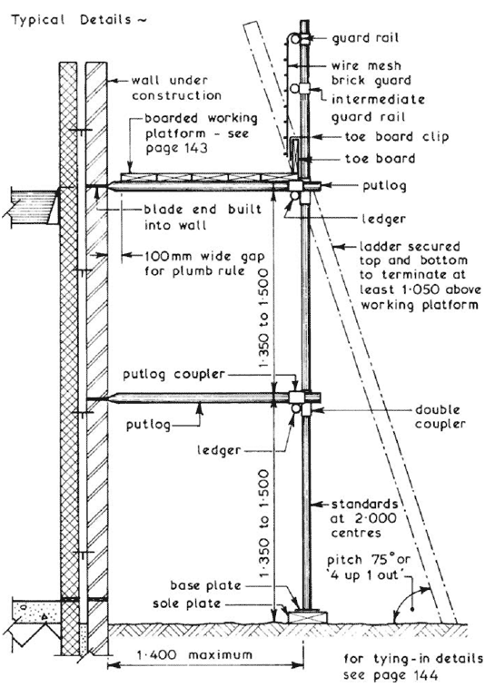
Putlog Scaffolds ~ these are scaffolds which have an outer row of standards joined together by ledgers which in turn support the transverse putlogs which are built into the bed joints or perpends as the work proceeds, they are therefore only suitable for new work in bricks or blocks.

Putlog Scaffolds ~
Independent Scaffolds ~ these are scaffolds which have two rows of standards each row joined together with ledgers which in turn support the transverse transoms. The scaffold is erected clear of the existing or proposed building but is tied to the building or structure at suitable intervals

Independent Scaffolds

Working Platforms ~ these are close boarded or plated level surfaces at a height at which work is being carried out and they must provide a safe working place of sufficient strength to support the imposed loads of operatives and/or materials. All working platforms above the ground levelmust be fittedwith a toe board and a guard rail.

Working Platforms
Tying-in ~ all putlog and independent scaffolds should be tied securely to the building or structure at alternate lift heights vertically and at not more than 6„000 centres horizontally.

Putlogs should not be classified as ties. Suitable tying-in methods include connecting to tubes fitted between sides of window openings or to internal tubes fitted across window openings, the former method should not be used for more than 50% of the total number of ties. If there is an insufficient number of window openings for the required number of ties external rakers should be used.

Tying-in
Mobile Scaffolds ~ otherwise known asmobile tower scaffolds. They can be assembled from pre-formed framing components or from standard scaffold tube and fittings. Used mainly for property maintenance. Must not be moved whilst occupied by persons or equipment.

Mobile Scaffolds

Some basic fittings ~

Some basic fittings

Sunday, February 16, 2014

Roads-Kerbs, Pavings and Edgings

Available sections - manufactured in 915 mm lengths from silver/grey aggregate concrete.


Concrete paving flags - BS dimensions:


Tactile flags - manufactured with a blistered (shown) or ribbed surface. Used in walkways to provide warning of hazards or to enable recognition of locations for people whose visibility is impaired. See also, Department of Transport Disability Circular DU 1/86[1], for uses and applications.

Ref. BS EN 1339: Concrete paving flags. Requirements and test methods.

Landscaping ~ in the context of building works this would involve reinstatement of the site as a preparation to the landscaping in the form of lawns, paths, pavings, flower and shrub beds and tree planting. The actual planning, lawn laying and planting activities are normally undertaken by a landscape subcontractor. The main contractor's work would involve clearing away all waste and unwanted materials, breaking up and levelling surface areas, removing all unwanted vegetation, preparing the subsoil for and spreading topsoil to a depth of at least 150mm.

Services ~ the actual position and laying of services is the responsibility of the various service boards and undertakings. The best method is to use the common trench approach, avoid as far as practicable laying services under the highway.

Roads - Footpaths

Typical Examples

Wednesday, February 12, 2014

Road Construction

Road Construction ~ within the context of building operations roadworks usually consist of the construction of small estate roads, access roads and driveways together with temporary roads laid to define site circulation routes and/or provide a suitable surface for plant movements. The construction of roads can be considered under three headings:-

1. Setting out.
2. Earthworks.
3. Paving Construction.

Setting Out Roads ~ this activity is usually carried out after the topsoil has been removed using the dimensions given on the layout drawing(s). The layout could include straight lengths junctions, hammer heads, turning bays and intersecting curves.

Straight Road Lengths † these are usually set out from centre lines which have been established by traditional means

Road Construction

Earthworks ~ this will involve the removal of topsoil together with any vegetation, scraping and grading the required area down to formation level plus the formation of any cuttings or embankments. Suitable plant for these operations would be tractor shovels fitted with a 4 in 1 bucket: graders and bulldozers. The soil immediately below the formation level is called the subgrade whose strength will generally decrease as its moisture content rises therefore if it is to be left exposed for any length of time protection may be required. Subgrade protection may take the form of a covering of medium gauge plastic sheeting with 300mm laps or alternatively a covering of sprayed bituminous binder with a sand topping applied at a rate of 1 litre per m2. To preserve the strength and durability of the subgrade it may be necessary to install cut off subsoil drains alongside the proposed road.

Paving Construction ~ once the subgrade has been prepared and any drainage or other buried services installed the construction of the paving can be undertaken. Paved surfaces can be either flexible or rigid in format. Flexible or bound surfaces are formed of materials applied in layers directly over the subgrade whereas rigid pavings consist of a concrete slab resting on a granular base.


Rigid Pavings ~ these consist of a reinforced or unreinforced in-situ concrete slab laid over a base course of crushed stone or similar material which has been blinded to receive a polythene sheet slip membrane. The primary objective of this membrane is to prevent grout loss from the in-situ slab.


Joints in Rigid Pavings ~ longitudinal and transverse joints are required in rigid pavings to:-

1 . Limit size of slab.
2. Limit stresses due to subgrade restraint.
3. Provide for expansion and contraction movements.

The main joints used are classified as expansion, contraction or longitudinal, the latter being the same in detail as the contraction joint differing only in direction. The spacing of road joints is determined by:-

1 . Slab thickness.
2. Whether slab is reinforced or unreinforced.
3. Anticipated traffic load and flow rate.
4. Temperature at which concrete is laid