Tuesday, December 24, 2013

CONSTRUCTION - MATERIALS TESTING - CONCRETE

Non destructive testing of concrete. Also known as in-place or in-situ tests.

Changes over time and in different exposures can be monitored.

References: BS 6089: Guide to assessment of concrete strength in existing structures; BS 1881: Testing concrete. BS EN 13791: Assessment of in-situ compressive strength in structures and pre-cast concrete components.

Provides information on: strength in-situ, voids, flaws, cracks and deterioration.

Rebound hammer test - attributed to Ernst Schmidt after he devised the impact hammer in 1948. It works on the principle of an elastic mass rebounding off a hard surface. Varying surface densities will affect impact and propagation of stress waves. These can be recorded on a numerical scale known as rebound numbers. It has limited application to smooth surfaces of concrete only. False results may occur where there are local variations in the concrete, such as a large piece of aggregate immediately below the impact surface. Rebound numbers can be graphically plotted to correspond with compressive strength.

Ref: BS EN 12504-2: Testing concrete in structures.

SCHMIDT HAMMER

Penetration or Windsor probe test ~ there are various interpretations of this test. It is a measure of the penetration of a steel alloy rod, fired by a predetermined amount of energy into concrete. In principle, the depth of penetration is inversely proportional to the concrete compressive strength. Several recordings are necessary to obtain a fair assessment and some can be discarded particularly where the probe cannot penetrate some dense aggregates. The advantage over the rebound hammer is provision of test results at a greater depth (up to 50mm).

Pull out test ~ this is not entirely non destructive as there will be some surface damage, albeit easily repaired. A number of circular bars of steel with enlarged ends are cast into the concrete as work proceeds. This requires careful planning and location of bars with corresponding voids provided in the formwork. At the appropriate time, the bar and a piece of concrete are pulled out by tension jack. Although the concrete fails in tension and shear, the pull out force can be correlated to the compressive strength of the concrete.

Testing concrete

Ref: BS 1881-207: Testing concrete. Recommendations for the assessment of concrete strength by near-to-surface tests.

Vibration test ~ a number of electronic tests have been devised, which include measurement of ultrasonic pulse velocity through concrete. This applies the principle of recording a pulse at predetermined frequencies over a given distance. The apparatus includes transducers in contact with the concrete, pulse generator, amplifier, and time measurement to digital display circuit. For converting the data to concrete compressive strength, see BS EN 12504-4: Testing concrete. Determination of ultrasonic pulse velocity.

A variation, using resonant frequency, measures vibrations produced at one end of a concrete sample against a receiver or pick up at the other. The driving unit or exciter is activated by a variable frequency oscillator to generate vibrations varying in resonance, depending on the concrete quality. The calculation of compressive strength by conversion of amplified vibration data is by formulae found in BS 1881-209: Testing concrete. Recommendations for the measurement of dynamic modulus of elasticity.

RESONANT FREQUENCY TEST

Other relevant standards:-

BS 1881-122: Testing concrete. Method for determination of water absorption.
BS 1881-124: Testing concrete. Methods for analysis of hardened concrete.
BS EN 12390-7: Testing hardened concrete. Density of hardened concrete.

Monday, December 23, 2013

CONSTRUCTION - MATERIALS TESTING

Site Tests ~ the majority of materials and components arriving on site will conform to the minimum recommendations of the appropriate British Standard and therefore the only tests which need be applied are those of checking quantity received against amount stated on the delivery note, ensuring quality is as ordered and a visual inspection to reject damaged or broken goods. The latter should be recorded on the delivery note and entered in the site records. Certain site tests can however be carried out on some materials to establish specific data such as the moisture content of timber which can be read direct from a moisture meter.

Other simple site tests are given in the various British Standards to ascertain compliance with the recommendations, such as tests for dimensional tolerances and changes given in BS EN 771-1 and BS EN 772-16 which cover random sampling of clay bricks of up to 10 units. An alternative site test can be carried out by measuring a sample of 24 bricks taken at random from a delivered load thus:-


Site Test ~ apart from the test outlined on page 83 site tests on materials which are to be combined to form another material such as concrete can also be tested to establish certain properties which if not known could affect the consistency and/or quality of the final material.

Typical Example ~ Testing Sand for Bulking This data is required when batching concrete by volume † test made at commencement of mixing and if change in weather


Therefore volume of sand should be increased by 21% over that quoted in the specification NB. a given weight of saturated sand will occupy the same space as when dry but more space when damp

Silt Test for Sand ~ the object of this test is to ascertain the cleanliness of sand by establishing the percentage of silt present in a natural sand since too much silt will weaken the concrete


Obtaining Samples for Laboratory Testing ~ these tests may be required for checking aggregate grading by means of a sieve test, checking quality or checking for organic impurities but whatever the reason the sample must be truly representative of the whole:-


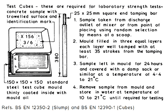
Concrete requires monitoring by means of tests to ensure that subsequent mixes are of the same consistency and this can be carried out on site by means of the slump test and in a laboratory by crushing test cubes to check that the cured concrete has obtained the required designed strength.


The slump cone is filled to a quarter depth and tamped 25 times - filling and tamping is repeated three more times until the cone is full and the top smoothed off. The cone is removed and the slump measured, for consistent mixes the slump should remain the same for all samples tested. Usual specification 50mm or 75mm slump.

CONSTRUCTION - MATERIALS STORAGE

Storage of Materials ~ this can be defined as the provision of adequate space, protection and control for building materials and components held on site during the construction process. The actual requirements for specific items should be familiar to students who have completed studies in construction technology at an introductory level but the need for storage and control of materials held on site can be analysed further:-

1. Physical Properties - size, shape, weight and mode of delivery will assist in determining the safe handling and stacking method(s) to be employed on site, which in turn will enable handling and storage costs to be estimated.
 
2. Organisation - this is the planning process of ensuring that all the materials required are delivered to site at the correct time, in sufficient quantity, of the right quality, the means of unloading is available and that adequate space for storage or stacking has been allocated.

3. Protection - building materials and components can be classified as durable or non-durable, the latter will usually require some form of weather protection to prevent deterioration whilst in store.

4. Security - many building materials have a high resale and/or usage value to persons other than those for whom they were ordered and unless site security is adequate material losses can become unacceptable.

5. Costs - to achieve an economic balance of how much expenditure can be allocated to site storage facilities the following should be taken into account:-

a. Storage areas, fencing, racks, bins, etc.
b. Protection requirements.
c. Handling, transporting and stacking requirements.
d. Salaries and wages of staff involved in storage of materials and components.
e. Heating and/or lighting if required.
f. Allowance for losses due to wastage, deterioration, vandalism and theft.
g. Facilities to be provided for subcontractors.

6. Control - checking quality and quantity of materials at delivery and during storage period, recording delivery and issue of materials and monitoring stock holdings.

Site Storage Space ~ the location and size(s) of space to be allocated for any particular material should be planned by calculating the area(s) required and by taking into account all the relevant factors before selecting the most appropriate position on site in terms of handling, storage and convenience. Failure to carry out this simple planning exercise can result in chaos on site or having on site more materials than there is storage space available.

Calculation of Storage Space Requirements ~ each site will present its own problems since a certain amount of site space must be allocated to the units of accommodation, car parking, circulation and working areas, therefore the amount of space available for materials storage may be limited. The size of the materials or component being ordered must be known together with the proposed method of storage and this may vary between different sites of similar building activities. There are therefore no standard solutions for allocating site storage space and each site must be considered separately to suit its own requirements.

Typical Examples ~

Bricks - quantity = 15,200 to be delivered in strapped packs of 380 bricks per pack each being 1100mm wide X 670mm long X 850mm high. Unloading and stacking to be by forklift truck to form 2 rows 2 packs high.


Areas for other materials stored on site can be calculated using the basic principles contained in the examples above.

Site Allocation for Materials Storage ~ the area and type of storage required can be determined as shown on pages 100 to 102, but the allocation of an actual position on site will depend on:-

1. Space available after areas for units of accommodation have been allocated.
2. Access facilities on site for delivery, vehicles.
3. Relationship of storage area(s) to activity area(s) - the distance between them needs to be kept as short as possible to reduce transportation needs in terms of time and costs to the minimum. Alternatively storage areas and work areas need to be sited within the reach of any static transport plant such as a tower crane.
4. Security - needs to be considered in the context of site operations, vandalism and theft.
5. Stock holding policy - too little storage could result in delays awaiting for materials to be delivered, too much storage can be expensive in terms of weather and security protection requirements apart from the capital used topurchase the materials stored on site.


Bricks ~ may be supplied loose or strapped in unit loads and stored on timber pallets


Drainage Pipes ~ supplied loose or strapped together on timber pallets


Gullies etc., should be stored upside down and supported to remain level

Saturday, December 21, 2013

CONSTRUCTION - SITE STORAGE

Site Storage ~ materials stored on site prior to being used or fixed may require protection for security reasons or against the adverse effects which can be caused by exposure to the elements.

Small and Valuable Items ~ these should be kept in a secure and lockable store. Similar items should be stored together in a rack or bin system and only issued against an authorised requisition.

Large or Bulk Storage Items ~ for security protection these items can be stored within a lockable fenced compound. The form of fencing chosen may give visual security by being of an open nature but these are generally easier to climb than the close boarded type of fence which lacks the visual security property.

Typical Storage Compound Fencing ~

Close boarded fences can be constructed on the same methods used for hoardings - see pages 92 & 93.

Alternative Fence Types ~ woven wire fence, strained wire fence, cleft chestnut pale fence, wooden palisade fence, wooden post and rail fence and metal fences † see BS 1722: Fences, for details.

CONSTRUCTION - SITE HEALTH AND WELFARE REQUIREMENTS

The requirements for health and wellbeing of persons on construction sites are enforced by the Health and Safety Executive, through the Health and Safety at Work etc. Act 1974 and the Construction (Health, Safety and Welfare) Regulations 1996. The following minimum requirements apply and the numbers of persons on sitewere established by theConstructionRegulations of 1966.

CONSTRUCTION - SITE OFFICE ACCOMMODATION

Office Accommodation ~ the arrangements for office accommodation to be provided on site is a matter of choice for each individual contractor. Generally separate offices would be provided for site agent, clerk of works, administrative staff, site surveyors and sales staff.

The minimum requirements of such accommodation is governed by the Offices, Shops and Railway Premises Act 1963 unless they are ~

1 . Mobile units in use for not more then 6 months.
2. Fixed units in use for not more than 6 weeks.
3. Any type of unit in use for not more than 21 man hours per week.
4. Office for exclusive use of self employed person.
5. Office used by family only staff.

Sizing Example ~

Office for site agent and assistant plus an allowance for 3 visitors.
Assume an internal average height of 2.400.
Allow 3.7m2 minimum per person and 11.5m3 minimum per person.
Minimum area = 5 3.7 = 18.5m2
Minimum volume = 5 11.5 = 57.5m3
Assume office width of 3.000 then minimum length required is


Typical Example ~

Portable cabin with four adjustable steel legs with attachments for stacking. Panelling of galvanised steel sheet and rigid insulation core. Plasterboard inner lining to walls and ceiling. Pyro-shield windows with steel shutters and a high security steel door.

Ref. Fire prevention on construction sites † the joint code of practice on protection from fire of construction sites and buildings undergoing renovation. Published by Construction Confederation and The Fire Protection Association.

Wednesday, December 18, 2013

ELECTRICAL SUPPLY TO BUILDING SITES

Electrical Supply to Building Sites ~ a supply of electricity is usually required at an early stage in the contract to provide light and power to the units of accommodation. As the work progresses power could also be required for site lighting, hand held power tools and large items of plant. The supply of electricity to a building site is the subject of a contract between the contractor and the local area electricity company who will want to know the date when supply is required; site address together with a block plan of the site; final load demand of proposed building and an estimate of the maximum load demand in kilowatts for the construction period. The latter can be estimated by allowing 10W/m2 of the total floor area of the proposed building plus an allowance for high load equipment such as cranes. The installation should be undertaken by a competent electrical contractor to ensure that it complies with all the statutory rules and regulations for the supply of electricity to building sites.

Typical Supply and Distribution Equipment ~


The units must be strong, durable and resistant to rain penetration with adequate weather seals to all access panels and doors. All plug and socket outlets should be colour coded :- 400V † red; 230V † blue; 110V † yellow.

Tuesday, December 17, 2013

SITE LIGHTING - CONSTRUCTION

Site Lighting ~ this can be used effectively to enable work to continue during periods of inadequate daylight. It can also be used as a deterrent to would-be trespassers. Site lighting can be employed externally to illuminate the storage and circulation areas and internally for general movement and for specific work tasks. The types of lamp available range from simple tungsten filament lamps to tungsten halogen and discharge lamps. The arrangement of site lighting can be static where the lamps are fixed to support poles or mounted on items of fixed plantsuch as scaffolding and tower cranes. Alternatively the lamps can be sited locally where the work is in progress by being mounted on a movable support or hand held with a trailing lead. Whenever the position of site lighting is such that it can be manhandled it should be voltage of 110V single phase as opposed to the mains voltage of 230V.

To plan an adequate system of site lighting the types of activity must be defined and given an illumination target value which is quoted in lux (lx). Recommended minimum target values for building activities are:-


Such target values do not take into account deterioration, dirt or abnormal conditions therefore it is usual to plan for at least twice the recommended target values. Generally the manufacturers will provide guidance as to the best arrangement to use in any particular situation but lamp requirements can be calculated thus:-


After choosing lamp type to be used:-


Typical Site Lighting Arrangement:-


Walkway and Local Lighting ~ to illuminate the general circulation routes bulkhead and/or festoon lighting could be used either on a standard mains voltage of 230V or on a reduced voltage of 110V.

For local lighting at the place of work hand lamps with trailing leads or lamp fittings on stands can be used and positioned to give the maximum amount of illumination without unacceptable shadow cast.

HOARDINGS - SITE SURVEY

Hoardings ~ under the Highways Act 1980 a close boarded fence hoarding must be erected prior to the commencement of building operations if such operations are adjacent to a public footpath or highway. The hoarding needs to be adequately constructed to provide protection for the public, resist impact damage, resist anticipated wind pressures and adequately lit at night. Before a hoarding can be erected a licence or permit must be obtained from the local authority who will usually require 10 to 20 days notice. The licence will set out the minimum local authority requirements for hoardings and define the time limit period of the licence.

Saturday, December 14, 2013

CONSTRUCTION - SITE SECURITY

Site Security ~ the primary objectives of site security are †

1 . Security against theft.
2. Security from vandals.
3. Protection from innocent trespassers.

The need for and type of security required will vary from site to site according to the neighbourhood, local vandalism record and the value of goods stored on site. Perimeter fencing, internal site protection and night security may all be necessary.

Typical Site Security Provisions ~

SITE LAYOUT CONSIDERATIONS

General Considerations ~ before any specific considerations and decisions can be made regarding site layout a general appreciation should be obtained by conducting a thorough site investigation at the pre-tender stage and examining in detail the drawings, specification and Bill of Quantities to formulate proposals of how the contract will be carried out if the tender is successful. This will involve a preliminary assessment of plant, materials and manpower requirements plotted against the proposed time scale in the form of a bar chart.

Access Considerations ~ this must be considered for both on- and off-site access. Routes to and from the site must be checked as to the suitability for transporting all the requirements for the proposed works. Access on site for deliveries and general circulation must also be carefully considered.

Typical Site Access Considerations ~


Storage Considerations ~ amount and types of material to be stored, security and weather protection requirements, allocation of adequate areas for storing materials and allocating adequate working space around storage areas as required, siting of storage areas to reduce double handling to a minimum without impeding the general site circulation and/or works in progress.

Accommodation Considerations ~ number and type of site staff anticipated, calculate size and select units of accommodation and check to ensure compliance with the minimum requirements of the Construction (Health, Safety and Welfare) Regulations 1996, select siting for offices to give easy and quick access for visitors but at the same time giving a reasonable view of the site, select siting for messroom and toilets to reduce walking time to a minimum without impeding the general site circulation and/or works in progress.

Temporary Services Considerations ~ what, when and where are they required? Possibility of having permanent services installed at an early stage and making temporary connections for site use during the construction period, coordination with the various service undertakings is essential.

Plant Considerations ~ what plant, when and where is it required? static or mobile plant? If static select the most appropriate position and provide any necessary hard standing, if mobile check on circulation routes for optimum efficiency and suitability, provision of space and hard standing for on-site plant maintenance if required.

Fencing and Hoarding Considerations ~ what is mandatory and what is desirable? Local vandalism record, type or types of fence and/or hoarding required, possibility of using fencing which is part of the contract by erecting this at an early stage in the contract.

Safety and Health Considerations ~ check to ensure that all the above conclusions from the considerations comply with the minimum requirements set out in the various Construction Regulations and in the Health and Safety at Work etc., Act 1974.

Typical Site Layout Example

Friday, December 13, 2013

SOIL ASSESSMENT AND TESTING

Soil Assessment ~ prior to designing the foundations for a building or structure the properties of the subsoil(s) must be assessed.

These processes can also be carried out to confirm the suitability of the proposed foundations. Soil assessment can include classification, grading, tests to establish shear strength and consolidation. The full range of methods for testing soils is given in BS 1377: Methods of test for soils for civil engineering purposes.

Classification ~ soils may be classified in many ways such as geological origin, physical properties, chemical composition and particle size. It has been found that the particle size and physical properties of a soil are closely linked and are therefore of particular importance and interest to a designer.

Particle Size Distribution ~ this is the percentages of the various particle sizes present in a soil sample as determined by sieving or sedimentation. BS 1377 divides particle sizes into groups as follows:-

Gravel particles - over 2mm
Sand particles - between 2mm and 0.06mm
Silt particles - between 0.06mm and 0.002mm
Clay particles - less than 0.002mm

The sand and silt classifications can be further divided thus:-

The results of a sieve analysis can be plotted as a grading curve thus:-


The results of a sieve analysis can be plotted as a grading curve thus:-


Triangular Chart ~ this provides a general classification of soils composed predominantly from clay, sand and silt. Each side of the triangle represents a percentage of material component. Following laboratory analysis, a sample's properties can be graphically plotted on the chart and classed accordingly. e.g. Sand † 70%. Clay † 10% and Silt † 20% = Sandy Loam.

Note:

Silt is very fine particles of sand, easily suspended in water. Loam is very fine particles of clay, easily dissolved in water.


Site Soil Tests ~ these tests are designed to evaluate the density or shear strength of soils and are very valuable since they do not disturb the soil under test. Three such tests are the standard penetration test, the vane test and the unconfined compression test all of which are fully described in BS 1377; Methods of test for soils for civil engineering purposes.

Standard Penetration Test ~ this test measures the resistance of a soil to the penetration of a split spoon or split barrel sampler driven into the bottom of a bore hole. The sampler is driven into the soil to a depth of 150mm by a falling standard weight of 65kg falling through a distance of 760mm. The sampler is then driven into the soil a further 300mm and the number of blows counted up to a maximum of 50 blows. This test establishes the relative density of the soil.

The results of this test in terms of number of blows and amounts of penetration will need expert interpretation.

Vane Test ~ this test measures the shear strength of soft cohesive  soils.  The  steel  vane  is  pushed  into  the  soft  clay  soil  and  rotated  by  hand at a constant rate. The amount  of  torque  necessary  for  rotation  is  measured and the soil shear strength  calculated as shown below.

This test can be carried out within a  lined  bore  hole  where  the  vane  is  pushed  into  the  soil  below  the  base  of the bore hole for a distance equal  to  three  times  the  vane  diameter  before  rotation  commences.

Alternatively the vane can be driven  or jacked to the required depth, the  vane being protected within a special  protection  shoe,  the  vane  is  then  driven  or  jacked  a  further  500mm  before rotation commences.


Unconfined Compression Test ~ this test can be used to establish the shear strength of a non-fissured cohesive soil sample using portable apparatus either on site or in a laboratory. The 75mm long 38mm diameter soil sample is placed in the apparatus and loaded in compression until failure occurs by shearing or lateral bulging. For accurate reading of the trace on the recording chart a transparent viewfoil is placed over the trace on the chart.

Typical Apparatus Details ~


NB. The shear strength of clay soils is only half of the compression strength values given above.

Laboratory Testing ~ tests for identifying and classifying soils with regard to moisture content, liquid limit, plastic limit, particle size distribution and bulk density are given in BS 1377.

Bulk Density ~ this is the mass per unit volume which includes mass of air or water in the voids and is essential information required for the design of retaining structures where the weight of the retained earth is an important factor.

Shear Strength ~ this soil property can be used to establish its bearing capacity and also the pressure being exerted on the supports in an excavation. The most popular method to establish the shear strength of cohesive soils is the Triaxial Compression Test. In principle this test consists of subjecting a cylindrical sample of undisturbed soil (75mm long 38mm diameter) to a lateral hydraulic pressure in addition to a vertical load. Three tests are carried out on three samples (all cut from the same large sample) each being subjected to a higher hydraulic pressure before axial loading is applied. The results are plotted in the form of Mohr's circles.

Shear Strength ~ this can be defined as the resistance offered by a soil to the sliding of one particle over another. A simple method of establishing this property is the Shear Box Test in which the apparatus consists of two bottomless boxes which are filled with the soil sample to be tested. A horizontal shearing force (S) is applied against a vertical load (W) causing the soil sample to shear along a line between the two boxes.


Consolidation of Soil ~ this property is very important in calculating the movement of a soil under a foundation. The laboratory testing apparatus is called an Oedometer.

EXCAVATION - BORE HOLE DATA

Bore Hole Data ~ the information obtained from trial pits or bore holes can be recorded on a pro forma sheet or on a drawing showing the position and data fromeach trial pit or bore hole thus:-


Bore holes can be taken on a 15„000 to 20„000 grid covering the whole site or in isolated positions relevant to the proposed foundation(s).


As a general guide the cost of site and soil investigations should not exceed 1% of estimated project costs.

Thursday, December 12, 2013

BUILDING SOIL INVESTIGATION

Site Investigation ~ this is an all embracing term covering every aspect of the site under investigation.

Soil Investigation ~ specifically related to the subsoil beneath the site under investigation and could be part of or separate from the site investigation.

Purpose of Soil Investigation ~

1. Determine the suitability of the site for the proposed project.
2. Determine an adequate and economic foundation design.
3. Determine the difficulties which may arise during the construction process and period.
4. Determine the occurrence and/or cause of all changes in subsoil conditions.

The above purposes can usually be assessed by establishing the physical, chemical and general characteristics of the subsoil by obtaining subsoil samples which should be taken from positions on the site which are truly representative of the area but are not taken from the actual position of the proposed foundations. A series of samples extracted at the intersection points of a 20„000 square grid pattern should be adequate for most cases.

Soil Samples ~ these can be obtained as disturbed or as undisturbed samples.

Disturbed Soil Samples ~ these are soil samples obtained from bore holes and trial pits. The method of extraction disturbs the natural structure of the subsoil but such samples are suitable for visual grading, establishing the moisture content and some laboratory tests. Disturbed soil samples should be stored in labelled airtight jars.

Undisturbed Soil Samples ~ these are soil samples obtained using coring tools which preserve the natural structure and properties of the subsoil. The extracted undisturbed soil samples are labelled and laid in wooden boxes for dispatch to a laboratory for testing. This method of obtaining soil samples is suitable for rock and clay subsoils but difficulties can be experienced in trying to obtain undisturbed soil samples in other types of subsoil.

The test results of soil samples are usually shown on a drawing which gives the location of each sample and the test results in the form of a hatched legend or section.

Depth of Soil Investigation ~ before determining the actual method of obtaining the required subsoil samples the depth to which the soil investigation should be carried out must be established. This is usually based on the following factors †

1. Proposed foundation type.
2. Pressure bulb of proposed foundation.
3. Relationship of proposed foundation to other foundations.


Pressure bulbs of less than 20% of original loading at foundation level can be ignored † this applies to all foundation types.


Soil Investigation Methods ~ method chosen will depend on several factors †

1 . Size of contract.
2. Type of proposed foundation.
3. Type of sample required.
4. Type of subsoils which may be encountered.

As a general guide the most suitable methods in terms of investigation depth are †

1 . Foundations up to 3 000 deep † trial pits.
2. Foundations up to 30 000 deep † borings.
3. Foundations over 30 000 deep † deep borings and in-situ examinations from tunnels and/or deep pits

Typical Trail Pit Details ~


Boring Methods to Obtain Disturbed Soil Samples ~
 

1 . Hand or Mechanical Auger † suitable for depths up to 3 000 using a 150 or 200mm diameter flight auger.
2. Mechanical Auger † suitable for depths over 3 000 using a flight or Cheshire auger † a liner or casing is required for most granular soils and may be required for other types of subsoil.
3. Sampling Shells † suitable for shallow to medium depth borings in all subsoils except rock.

Typical details ~


Wash Boring ~ this is a method of removing loosened soil from a bore hole using a strong jet of water or bentonite which is a controlled mixture of fullers earth and water. The jetting tube is worked up and down inside the bore hole, the jetting liquid disintegrates the subsoil which is carried in suspension up the annular space to a settling tank. The settled subsoil particles can be dried for testing and classification. This method has the advantage of producing subsoil samples which have not been disturbed by the impact of sampling shells however it is not suitable for large gravel subsoils or subsoils which contain boulders.

Typical Wash Boring Arrangement  ~


Mud-rotary Drilling ~ this is a method which can be used for rock investigations where bentonite is pumped in a continuous flow down hollow drilling rods to a rotating bit. The cutting bit is kept in contact with the bore face and the debris is carried up the annular space by the circulating fluid. Core samples can be obtained using coring tools.

Core Drilling ~ water or compressed air is jetted down the bore hole through a hollow tube and returns via the annular space. Coring tools extract continuous cores of rock samples which are sent in wooden boxes for laboratory testing.

Wednesday, December 11, 2013

TRIAL PITS AND HAND AUGER HOLES

Purpose ~ primarily to obtain subsoil samples for identification, classification and ascertaining the subsoil's characteristics and properties. Trial pits and augered holes may also be used to establish the presence of any geological faults and the upper or lower limits of the water table.

TRIAL PITS

General use ~ dry ground which requires little or no temporary support to sides of excavation.

Subsidiary use~ to expose and/or locate underground services.

Advantages ~ subsoil can be visually examined in-situ † both disturbed and undisturbed samples can be obtained.

HAND AUGER HOLES

General use ~ dry ground but liner tubes could be used if required to extract subsoil samples at a depth beyond the economic limit of trial holes.

Advantages ~ generally a cheaper and simpler method of obtaining subsoil samples than the trial pit method.


Trial pits and holes should be sited so that the subsoil samples will be representative but not interfering with works.

BUILDING - SITE INVESTIGATIONS

Site Investigation For New Works ~ the basic objective of this form of site investigation is to collect systematically and record all the necessary data which will be needed or will help in the design and construction processes of the proposed work. The collected data should be presented in the form of fully annotated and dimensioned plans and sections. Anything on adjacent sites which may affect the proposed works or conversely anything appertaining to the proposed works which may affect an adjacent site should also be recorded.

Procedures ~

1 . Desk study
2. Field study or walk-over survey
3. Laboratory analysis (see pages 81†82 and 85†87)

Desk Study ~ collection of known data, to include:

• Ordnance Survey maps † historical and modern, note grid reference.
• Geological maps † subsoil types, radon risk.
• Site history † green-field/brown-field.
• Previous planning applications/approvals.
• Current planning applications in the area.
• Development restrictions † conservation orders.
• Utilities † location of services on and near the site.
• Aerial photographs.
• Ecology factors † protected wildlife.
• Local knowledge † anecdotal information/rights of way.
• Proximity of local land fill sites † methane risk.

Field Study ~ intrusive visual and physical activity to:

• Establish site characteristics from the desk study.
• Assess potential hazards to health and safety.
• Appraise surface conditions:
   * Trees † preservation orders.
   * Topography and geomorphological mapping.
• Appraise ground conditions:
   * Water table.
   * Flood potential † local water courses and springs.
   * Soil types.
   * Contamination † vegetation die-back.
   * Engineering risks † ground subsidence, mining, old fuel tanks.
   * Financial risks † potential for the unforeseen.
• Take subsoil samples and conduct in-situ tests.
• Consider the need for subsoil exploration, trial pits and bore holes.
• Appraise existing structures:
   * Potential for re-use/refurbishment.
   * Archaeological value/preservation orders.
   * Demolition † costs, health issues e.g. asbestos.

Tuesday, December 10, 2013

BUILDING - SITE SURVEY

Site Analysis - prior to purchasing a building site it is essential to conduct a thorough survey to ascertain whether the site characteristics suit the development concept. The following guidance forms a basic checklist:

* Refer to Ordnance Survey maps to determine adjacent features, location, roads, facilities, footpaths and rights of way.
* Conduct a measurement survey to establish site dimensions and levels.
* Observe surface characteristics, i.e. trees, steep slopes, existing buildings, rock outcrops, wells.
* Inquire of local authority whether preservation orders affect the site and if it forms part of a conservation area.
* Investigate subsoil. Use trial holes and borings to determine soil quality and water table level.
* Consider flood potential, possibilities for drainage of water table, capping of springs, filling of ponds, diversion of streams and rivers.
* Consult local utilities providers for underground and overhead services, proximity to site and whether they cross the site.
* Note suspicious factors such as filled ground, cracks in the ground, subsidence due to mining and any cracks in existing buildings.
* Regard neighbourhood scale and character of buildings with respect to proposed new development.
* Decide on best location for building (if space permits) with regard to `cut and fill', land slope, exposure to sun and prevailing conditions, practical use and access.

BUILDING - SITE SURVEY